Hacking the Data Bus in a Chinese Solar Generator
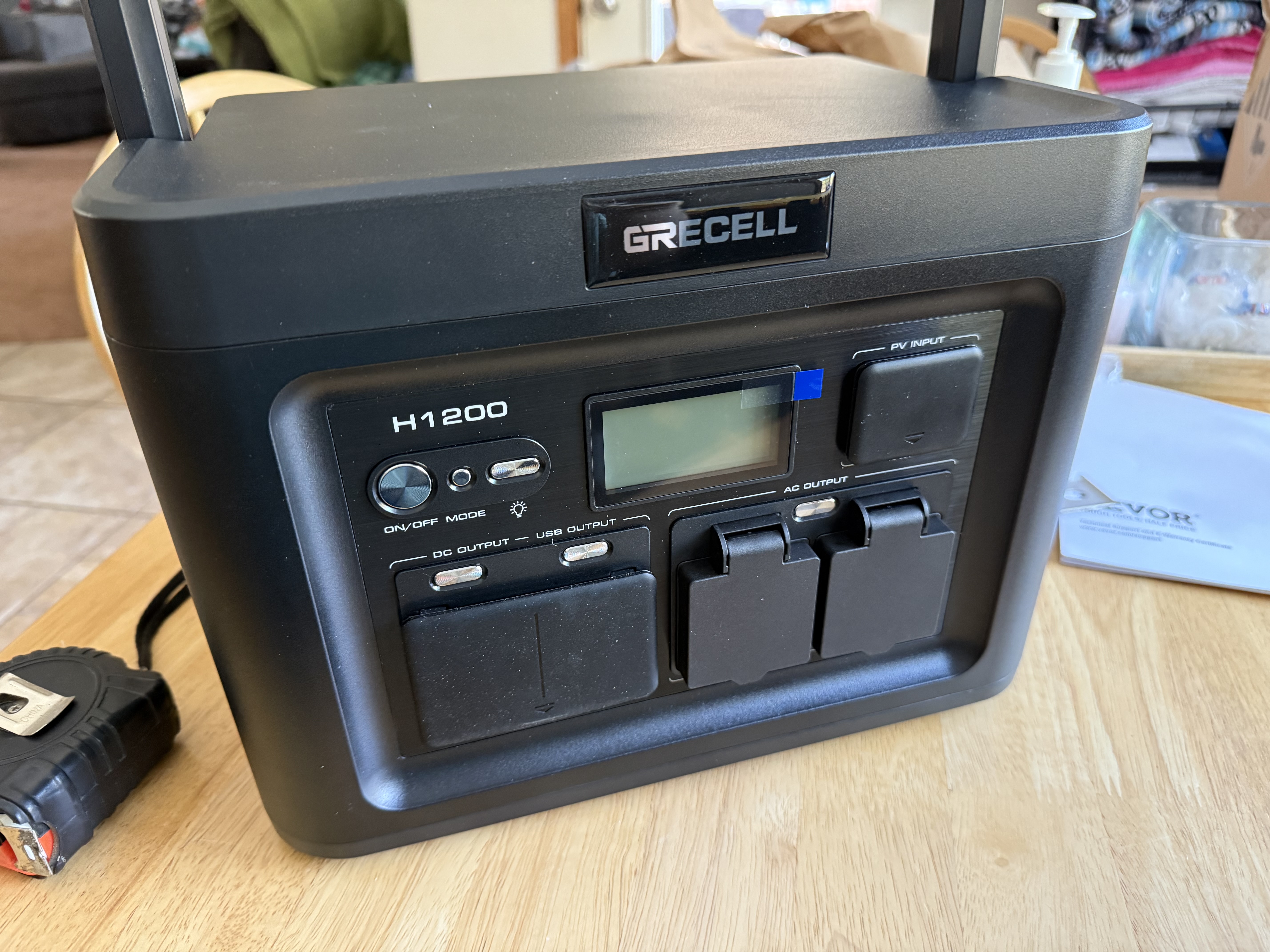
28 Apr 2026 devops automation hardware reverse-engineering solar modbus home-assistantI built an off-grid roadside camera relay for our neighborhood, and I needed one thing that the power station did not provide: data. The GRECELL H1200 had no app, no API, no Bluetooth, and no cloud integration. Just an LCD. Good enough for camping. Not good enough when you want proactive alerts before your cameras go dark.
So I did what any reasonable engineer does after a Monster and a bad idea: opened it.
This is the story of how that turned into a full reverse-engineering rabbit hole.
Why This Started
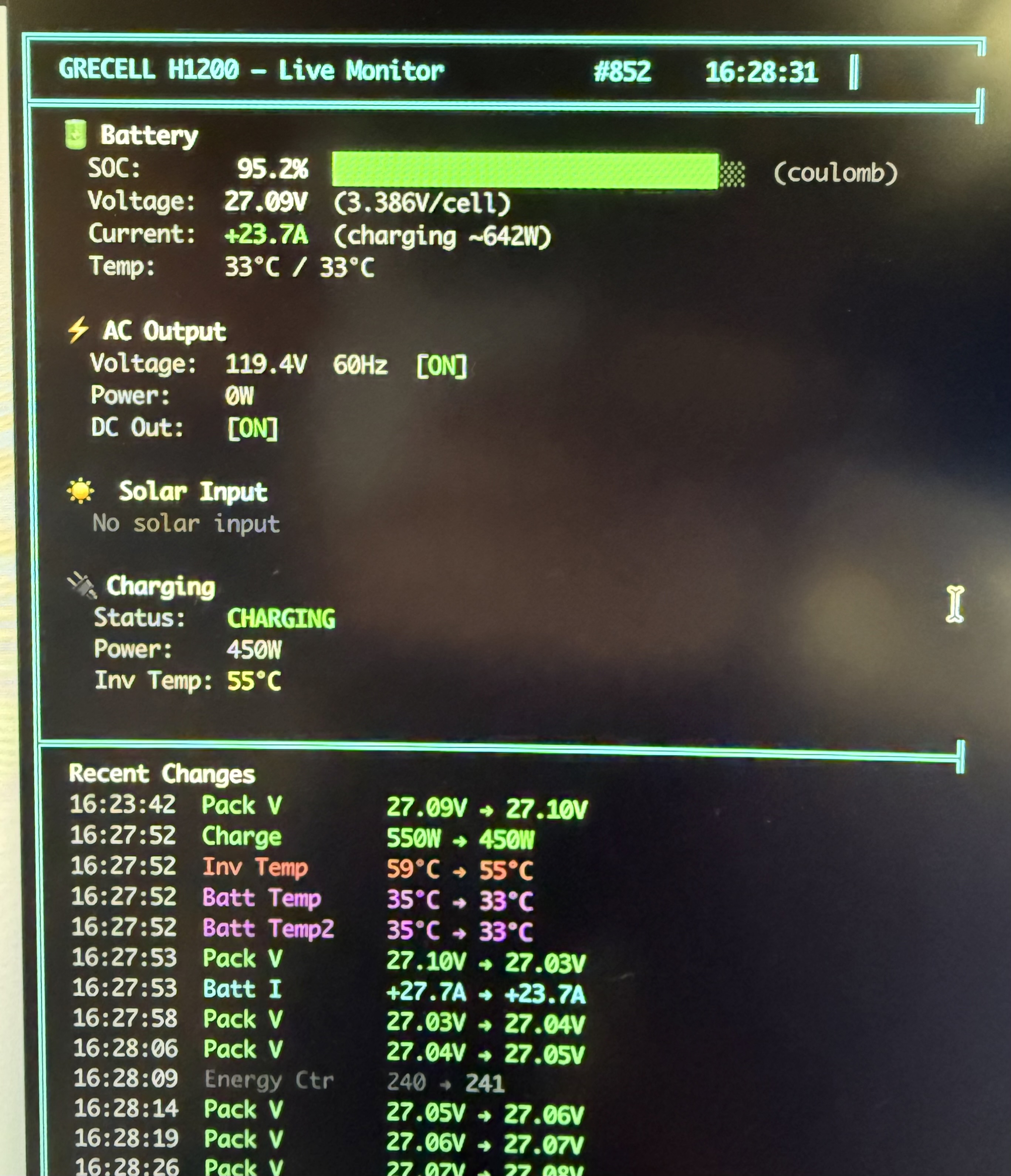
Here is the practical problem. I had a remote camera system running from solar, and I needed confidence that power would hold overnight, through cloudy days, and through weather swings. The H1200 could show status on its built-in LCD, but I needed those metrics in Home Assistant so I could alert, trend, and automate.
I wanted:
- Pack voltage and current
- Charge and load power
- Output state flags
- Temperatures
- A reliable SOC estimate for alerting
In other words, I wanted operational telemetry, not a periodic walk to the mailbox and a squint at tiny digits.
The First Obvious Attempt: Debug Headers
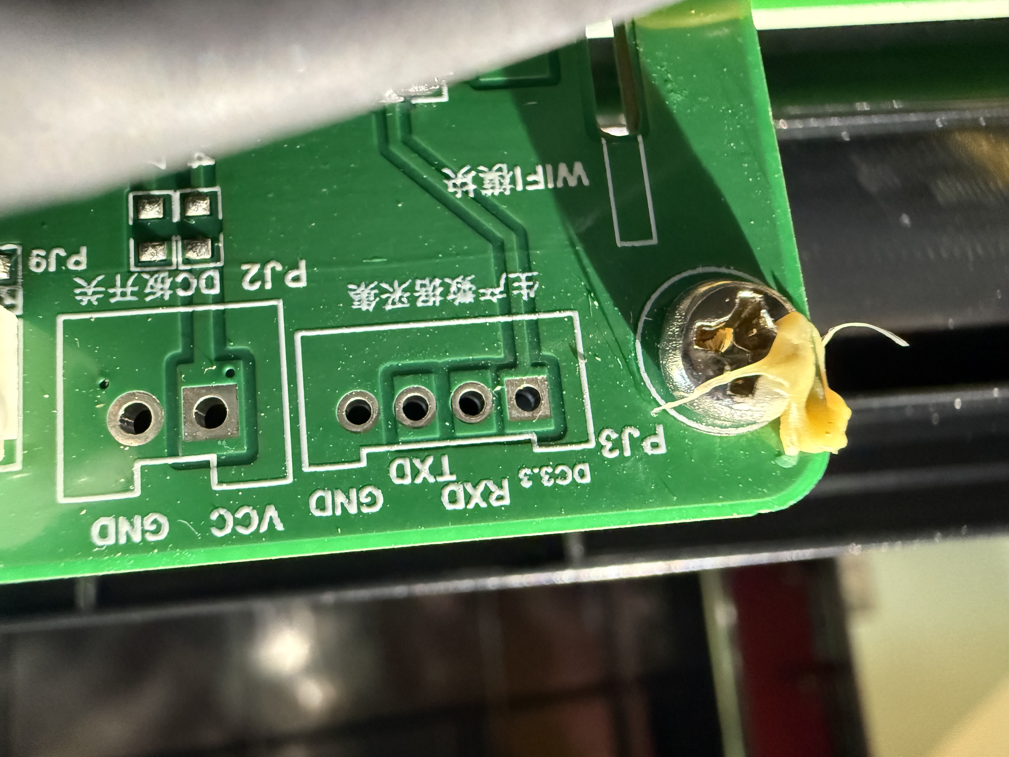
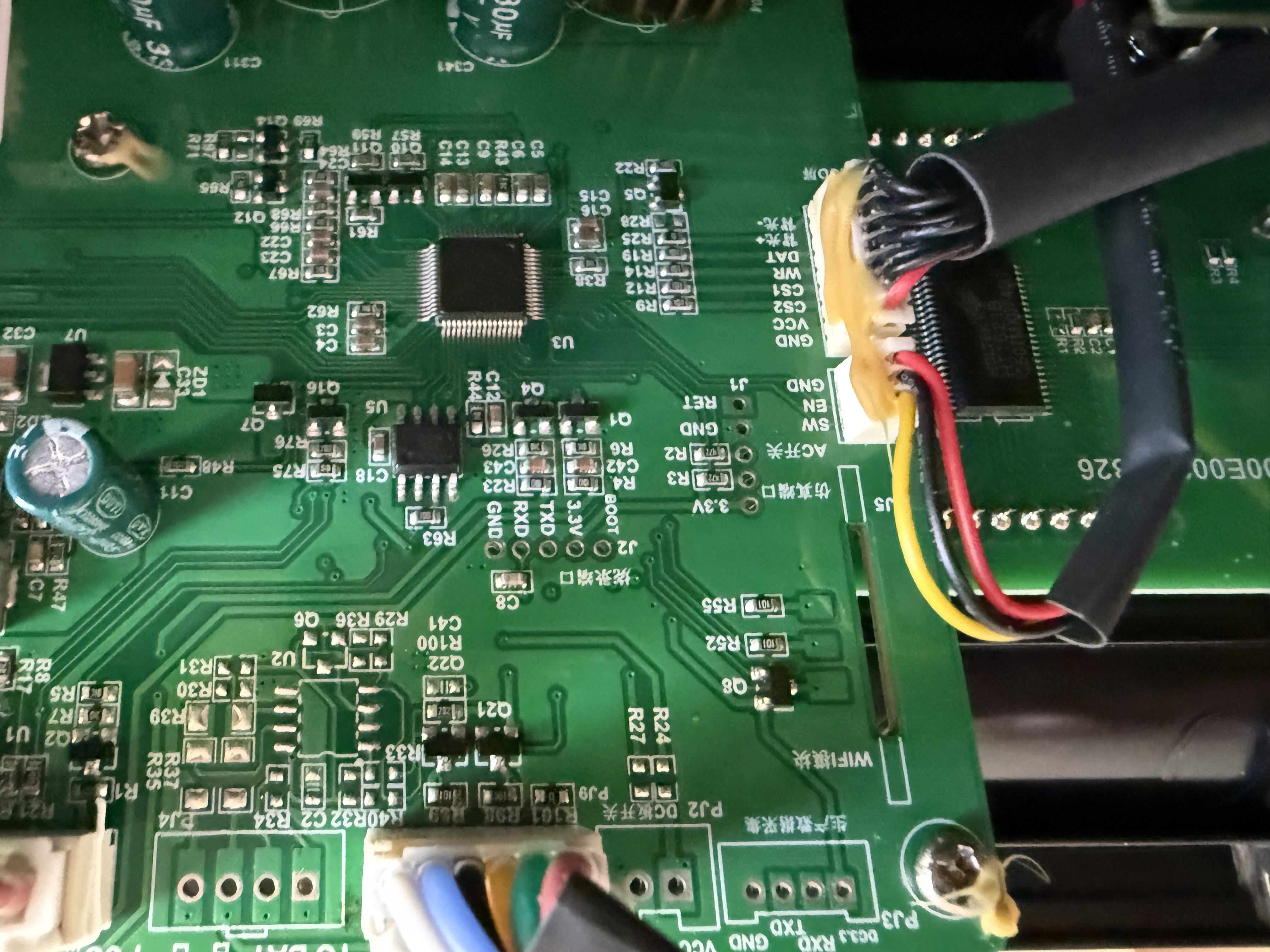
Once I opened the case, two headers immediately looked like the easy path:
PJ3with markings that translated to production data collectionJ2marked as flash/programming
Both had RX, TX, 3.3V, GND. It looked like a one-hour UART job.
Narrator: It was not a one-hour UART job.
PJ3: All Promise, No Payload
I soldered in headers, connected USB-TTL, tested common baud rates, and tried both passive listening and active command probing.
Nothing.
The pins were electrically alive, but the firmware looked like it was keeping the port dormant unless some missing companion module is detected at boot. So the most obvious data port was basically a decorative feature in this configuration.
J2: A Great Clue, but Still a Dead End
J2 was more interesting. At 9600 baud, it repeated frames like this:
~25004642E00200FD32\r
That was a useful clue pointing toward a Pylon/PACE style exchange, but it turned out to be outbound polling from the MCU. I could hear the unit asking questions, but not the BMS answers that contained the actual values.
So yes, this was progress. Also yes, still a dead end.
Signal Hunting Mode
At that point, I stopped assuming the labeled headers were my path and started following the real electrical path.
Scope probes went on the board-to-board lines between the main controller and the BMS daughter board.
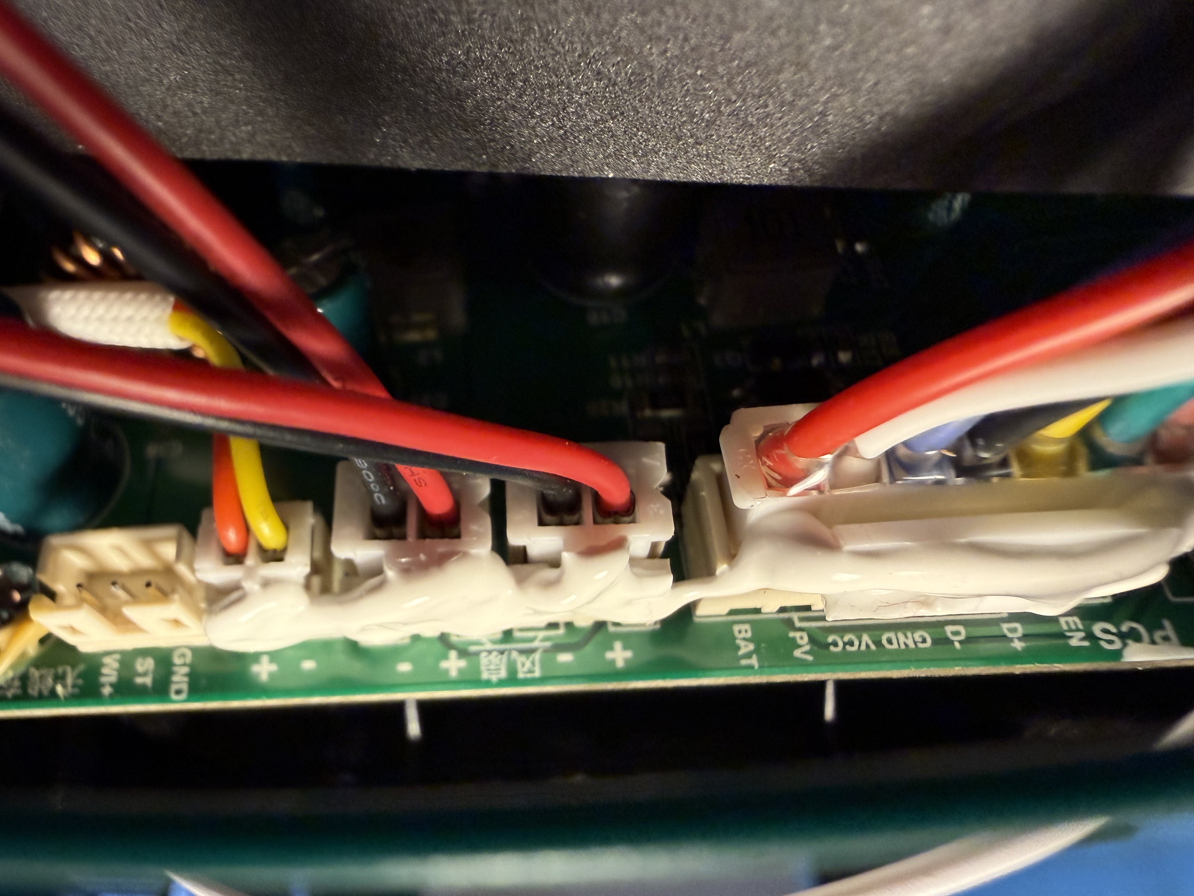
What showed up was textbook differential behavior: one line rising while the other fell, clean mirrored waveforms, and timing that lined up around 9600 baud.
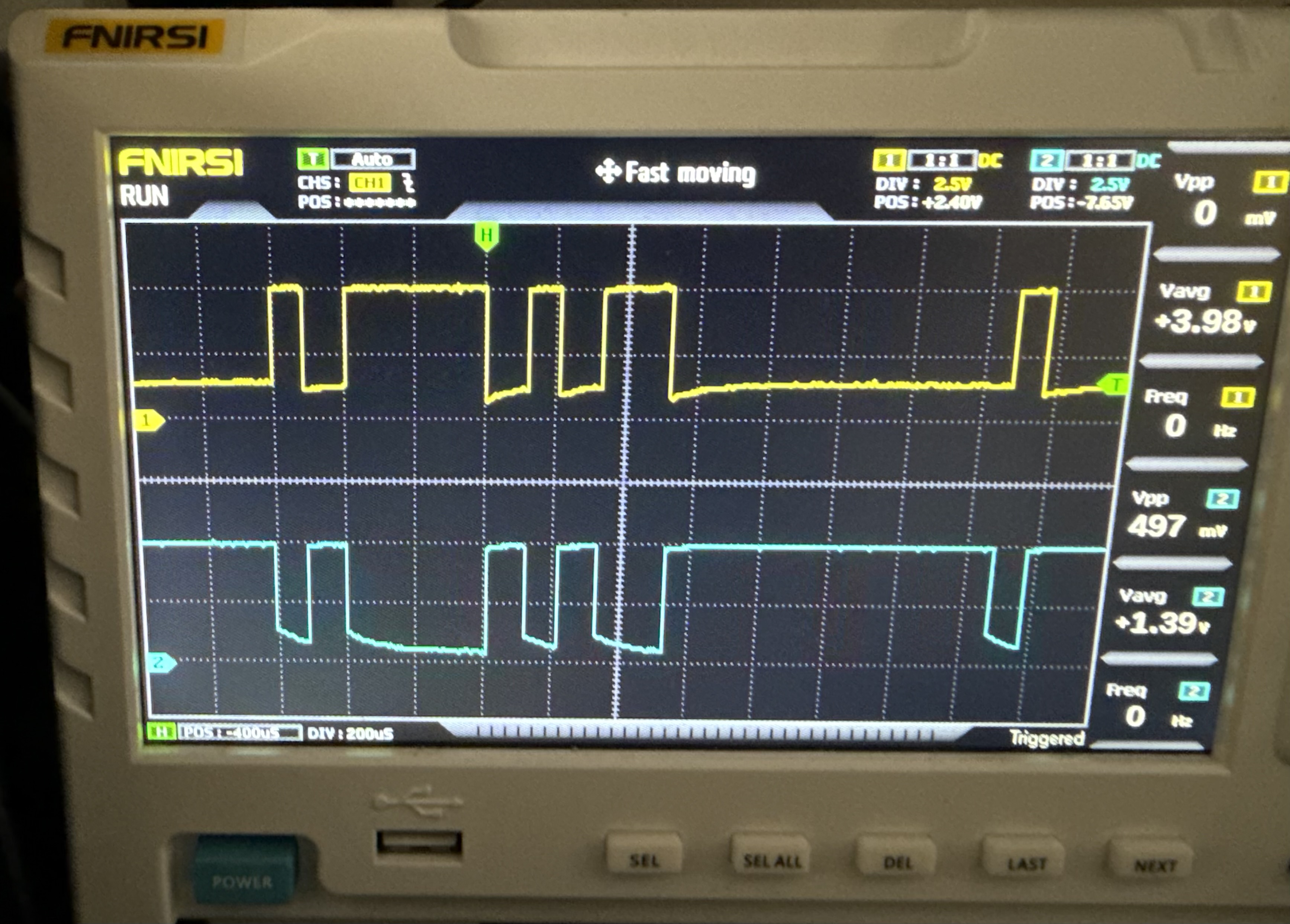
That was the moment the project clicked.
This was not TTL UART. This was RS485.
The Breakthrough: Tapping the Actual Bus
I swapped to an RS485 adapter and captured traffic directly on that link.
I expected to confirm Pylon based on the J2 clue. Instead, I got this:
01 03 0F A0 00 29 C5 52
01 03 52 ...
That is Modbus RTU. Cleanly.
The polling loop was stable and repetitive:
- Slave address
0x01 - Function
0x03(Read Holding Registers) - Start register
0x0FA0(4000) - Quantity
0x0029(41 registers) - Valid CRC16 framing
Roughly one full cycle per second.
At this point, I finally had the right bus, the right protocol, and repeatable captures.
If you want specs:
Turning Raw Registers Into Real Metrics
Finding traffic is the easy part. Decoding meaning is where the time goes.
I used controlled stimulus tests and changed one thing at a time:
- Add AC load and watch which registers jump
- Toggle AC/DC output buttons and track state flips
- Start charging and identify charge-related fields
- Observe thermal changes over time
That method quickly confirmed core operational data such as output power, charge power, state flags, and temperatures.
Then I expanded queries beyond the default polling block and found additional useful values, including pack voltage and signed battery current in extended ranges.
The Annoying Twist: SOC Was Missing
I burned a lot of time chasing SOC candidates. Several registers looked convincing until load tests exposed the truth: they tracked voltage behavior, not true state-of-charge.
The practical conclusion was:
- The displayed SOC is likely computed inside the main MCU
- That computed SOC is not published on the Modbus bus
So I built SOC estimation using coulomb counting from current over time:
SOC(Ah) += current(A) * dt(s) / 3600
SOC(%) = SOC(Ah) / 26.25Ah * 100
Seed from the LCD at startup, then recalibrate periodically. It is not mathematically perfect forever, but it is more than good enough for operational alerting.
What This Ended Up Looking Like
Hardware path:
- ESP32-S3-Ethernet board
- MAX485 transceiver
- Passive tap onto RS485 lines
Software path:
- ESPHome
modbus_controller - Home Assistant entities and automations
Useful references:
Summary and Key Takeaways
Here is the lesson in one line: labeled ports are hints, not truth.
Here is your action plan if you are doing similar reverse engineering:
- Start with documented headers, but verify assumptions fast.
- If data is partial or silent, follow physical traces and inspect waveforms.
- Confirm physical layer first, protocol second.
- Decode with controlled stimuli, not guesswork.
- Validate every claim with repeatable behavior.
- Plan for missing values by deriving what you need.
The fun part is that this started as a basic “I need battery alerts” task for a roadside camera setup and turned into protocol archaeology. The useful part is that it now produces reliable telemetry every day.
Comments