Building an Off-Grid Camera Relay System for a Rural Road
28 Apr 2026 ubiquiti devops automation security solar off-grid home-assistant raspberry-pi mqttI live out on a dead-end country road. Most days it is quiet, and that is exactly why we like it. The downside is that quiet roads attract people who assume nobody is watching. We started seeing trash dumping, roadside drinking, and other late-night nonsense at the end of the road.
Our neighbor group agreed we needed visibility, and as the neighborhood nerd, I decided to build a solution for us.
This post is the story of turning that idea into a working off-grid camera relay - from early design choices through a full hardware revision driven by real-world reliability problems.
The Brief: Build a Tiny Remote Site
Here were the non-negotiables:
- No utility power at the install location
- No trenching new cable
- Reliable network path back to the house
- Monitoring so we get alerts before downtime
That last one matters more than people think. A camera that silently died two days ago is basically decorative hardware.
Picking the Network Stack
Most of my gear is already Ubiquiti, so I stayed in that ecosystem and kept management simple.
Core networking:
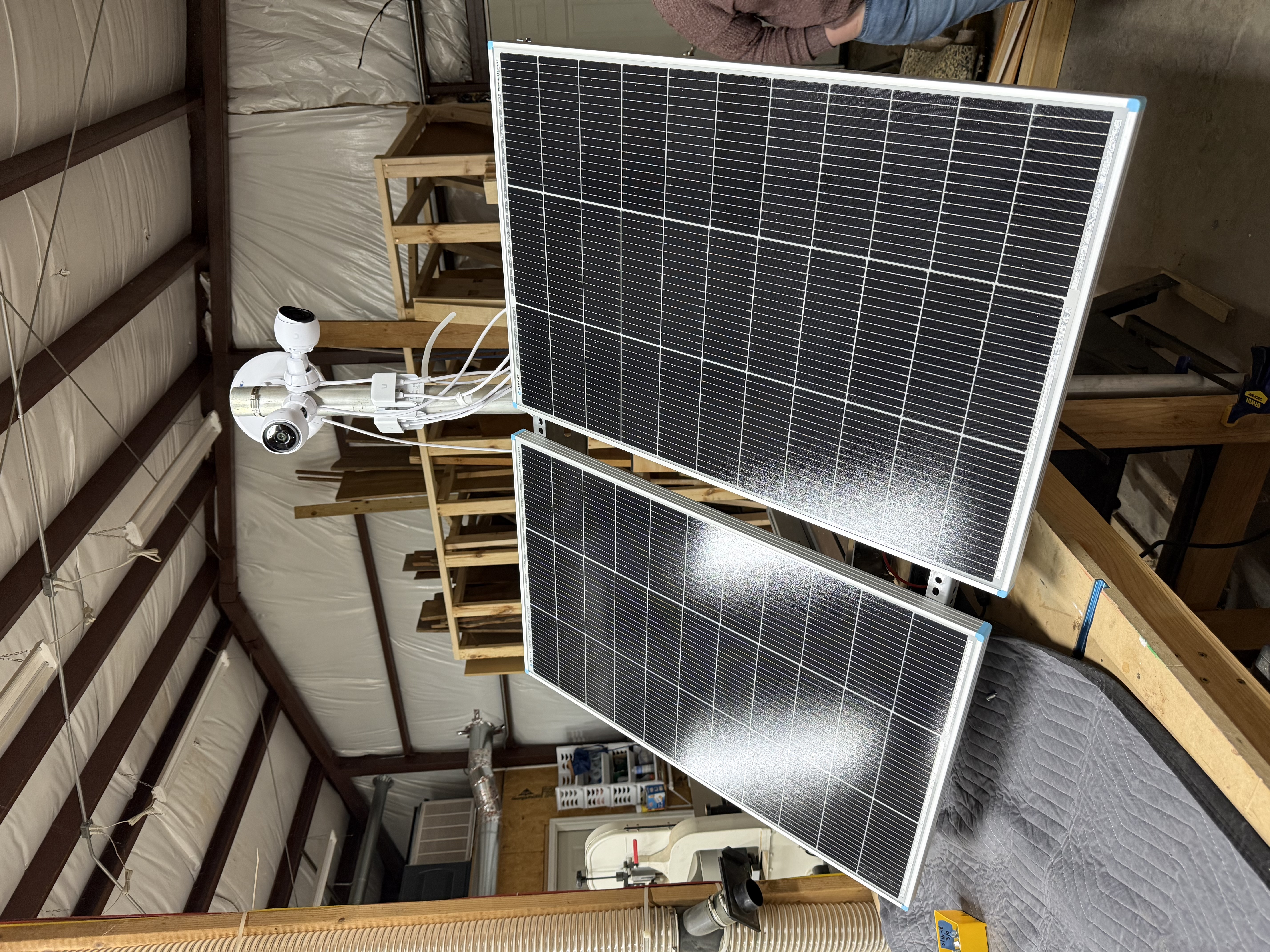
- 2x Ubiquiti Device Bridge Pro for the point-to-point link
- 2x Ubiquiti G5 Bullet for coverage
- 1x Ubiquiti USW-Flex as the remote switch
Power system (more on the evolution of this later):
- 2x 100W rigid solar panels in parallel
- GoKWh 100Ah LiFePO4 battery
- Renogy Wanderer 10A PWM charge controller
- 300W standalone inverter
- Raspberry Pi 3 B+ running a custom MQTT monitoring stack
The intent was simple: stable video path plus enough telemetry to know when something is drifting before it fails.
The Moment This Became a Power Project
Stop me if you have heard this one. You start with “just two cameras” and suddenly you are doing energy math on a whiteboard.
Estimated continuous load:
| Device | Power |
|---|---|
| 2 cameras | 8W |
| USW-Flex | 5W |
| bridge radio budget | ~8W to 19W depending on model |
| Total (typical) | ~21W |
Daily consumption:
21W * 24h = 504Wh/day
That single line drives almost every hardware choice after it.
I went with two 100W rigid panels because they are easier to mount permanently, easier to angle correctly, and less awkward than giant folding panel formats on a roadside pole.
Panel and Enclosure Placement
At one point, we explored mounting solar on the existing nearby structure rather than a dedicated post. It sounds clever until geometry and shading show up to ruin your day.
What made it a bad idea in practice:
- No clean flat surface for proper panel angle
- Directional compromise from fixed orientation
- Partial shading risks that can crush actual production
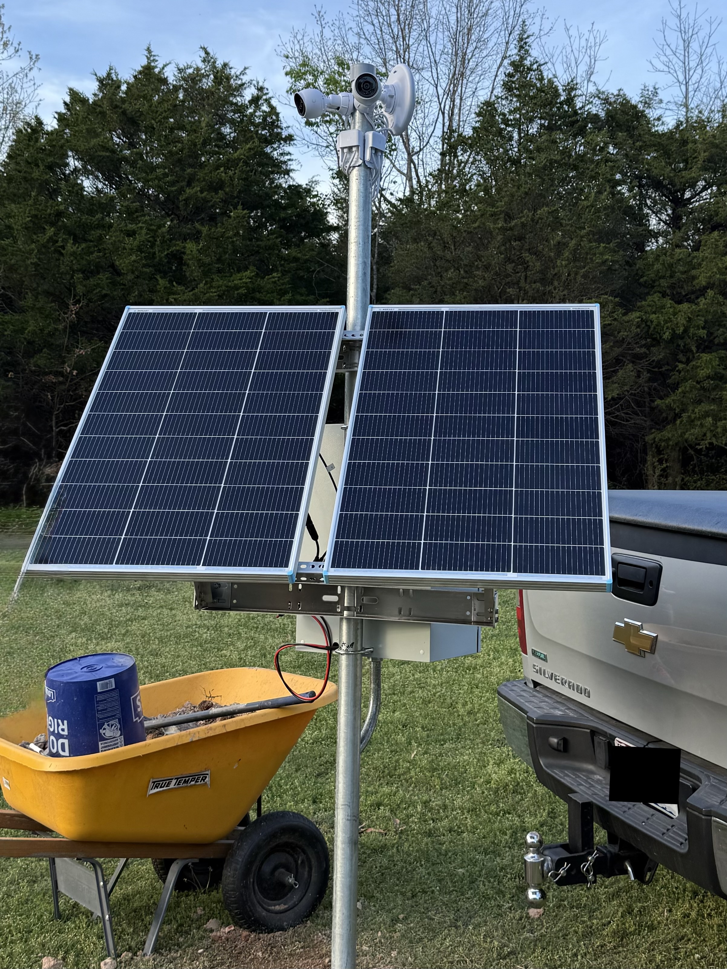
The better answer was boring and effective:
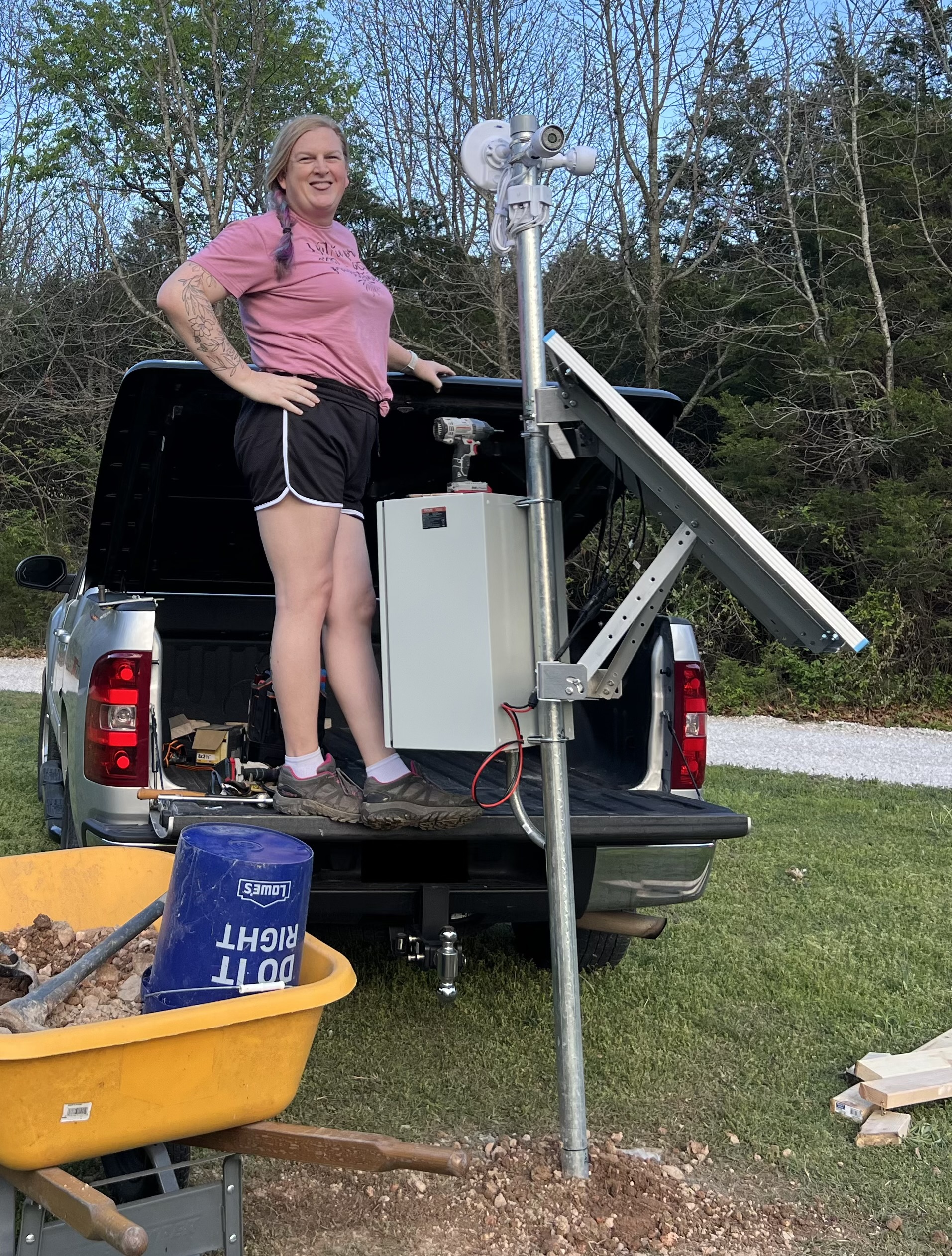
- Dedicated nearby post for the panels
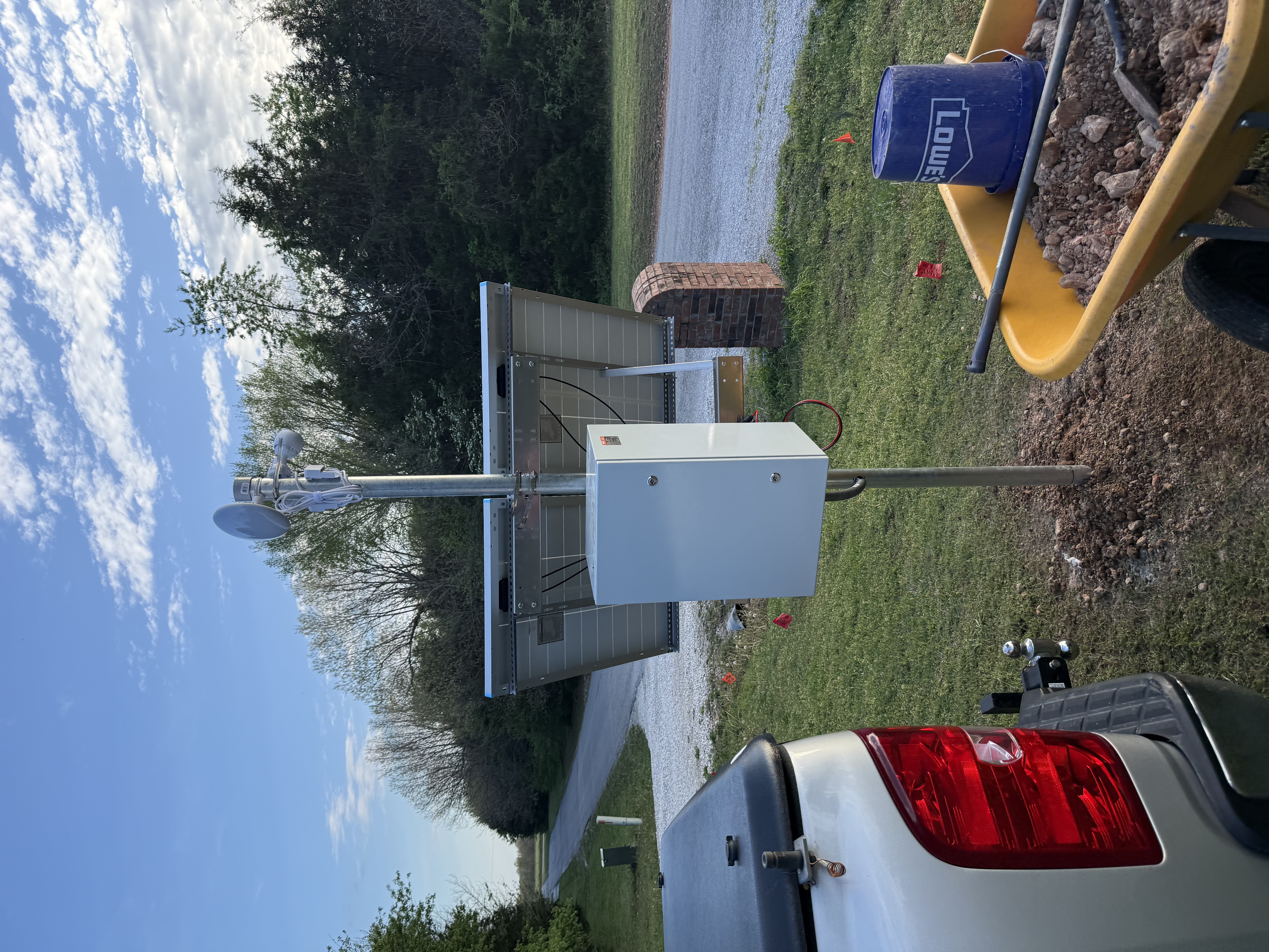
- Enclosure mounted directly to the same pole
- Short cable runs
Enclosure Reality Check
This was another area where theory and reality fought each other.
The enclosure needed to hold the battery, charge controller, inverter, switch, and the Pi while still allowing airflow and maintenance access. You can absolutely fit this class of build into a 24 x 16 x 12 weatherproof enclosure, but only if you verify internal dimensions. Product pages often advertise external dimensions, and that mismatch can be painful.
Quick checklist that saved headaches:
- Cable glands for solar and Ethernet ingress
- Clearance around the battery for airflow
- Backplate layout for controller, inverter, and switch before drilling
- Drip loops on every external cable entry
Because the enclosure is sealed and sitting in the sun, heat management is real. The Pi now controls a 12V exhaust fan via relay, with the BME280 sensor inside the enclosure providing temperature feedback. The fan kicks on at 60°C and shuts off at 55°C, with a periodic keep-alive pulse to prevent stagnation even on cooler days.
The GRECELL Chapter (A Story About Learning the Hard Way)
Here is the thing: the original build used a GRECELL H1200 all-in-one power station. It seemed like the right call at the time - integrated BMS, inverter, display, the whole package in one box.
The problem was reliability. The GRECELL had a habit of behaving unpredictably under sustained partial-state-of-charge cycling, which is exactly what a 24/7 outdoor load does to a battery. After enough headaches, I scrapped it and moved to proper solar components.
If you want the full story of what I learned poking around inside that unit, I wrote a separate post: Hacking the Data Bus in a Chinese Solar Generator.
The replacement stack:
- GoKWh 100Ah LiFePO4 - dedicated battery with a TDT BMS accessible over Bluetooth LE
- Renogy Wanderer 10A PWM - standalone charge controller with Modbus RTU over RS232
- 300W inverter - dumb box, no data interface, just does its job
Each component is now independently monitored. If something drifts, I know exactly which piece is misbehaving.
AC Injectors vs Custom DC-DC PoE Path
We considered the classic efficiency question: should we convert battery DC up to 24V/48V and feed PoE directly?
For this load, I chose AC injectors from the inverter and moved on with life.
Why:
- Simpler troubleshooting in the field
- Fewer custom points of failure
- Easy replacement with commodity parts
Yes, there is a conversion-efficiency tax. No, it was not the bottleneck in this project.
Telemetry: The Difference Between “Installed” and “Operated”
This is where the project got interesting. After replacing the GRECELL, I had three separate devices that needed monitoring. An ESP32 was no longer going to cut it.
The solution is a Raspberry Pi 3 B+ running a Python async service that publishes three independent devices to Home Assistant via MQTT auto-discovery.
GoKWh Battery (Bluetooth LE)
The GoKWh uses a TDT BMS that communicates over BLE. The monitoring script does a full scan-connect-authenticate-read-disconnect cycle every 60 seconds, which keeps things clean and avoids fighting with the manufacturer’s phone app for the BLE link.
Every poll publishes 19 entities to Home Assistant:
- Pack voltage, current, power
- State of charge and remaining capacity
- Charge cycle count
- Individual cell voltages (4 cells) and cell voltage delta
- BMS temperatures (3 sensors)
- Charge and discharge MOSFET state
- Protection status
The cell delta metric is particularly useful. A healthy pack should have cells within a few millivolts of each other. Drift there is an early warning of balance issues long before you see anything wrong in aggregate voltage.
Renogy Wanderer (RS232 Modbus RTU)
The Wanderer talks Modbus RTU over RS232. Entities are registered in HA and will report solar panel voltage/current/power, battery voltage, charge state, controller temperature, and load state once the RS232 hardware is wired in. For now they show as unavailable, which is intentional - at least the plumbing is in place.
Pi Management (Local GPIO / I²C)
The Pi itself reports:
- Enclosure temperature, humidity, and barometric pressure (BME280 on I²C)
- CPU temperature
- Cooling fan state (relay-controlled 12V fan)
- Enclosure door state (reed switch, normally-closed to GND)
The door sensor is surprisingly useful. It tells you immediately if someone opened the enclosure - whether that is you doing maintenance or something you did not expect.
Reliability Under the Hood
The Pi 3 B+’s onboard Bluetooth is notoriously finnicky. The monitoring script handles this with an escalating reset sequence: btmgmt power cycle, then rfkill block/unblock plus bluetooth service restart, then full system reboot as a last resort. Five consecutive BLE failures trigger the first level. It has never had to go past level two in production.
Each polling loop (battery, Pi, Renogy) runs as an independent async task with a supervisor that restarts dead tasks after 5 seconds. MQTT uses a Last Will and Testament so the battery shows as offline in HA if the script dies unexpectedly.
References:
Lightning and Surge Protection
If your setup includes outdoor Ethernet and exposed metal structure, lightning planning is mandatory, not optional.
Minimum baseline:
- Bond exposed metal structures appropriately
- Use outdoor-rated Ethernet surge suppression on exposed lines
- Keep grounding and surge paths intentional and inspectable
For Ubiquiti environments, the Ethernet Surge Protector is a practical starting point.
Summary and Key Takeaways
The high-level lesson is straightforward: this was not a camera purchase, it was a small infrastructure project. The second lesson is that all-in-one “convenient” hardware can cost you more in debugging time than proper purpose-built components.
Here is your action plan if you are building something similar:
- Do the power budget first.
- Use proper solar components (dedicated battery, dedicated charge controller) rather than all-in-one power stations.
- Optimize panel placement for sun and maintainability, not cleverness.
- Validate enclosure internals before buying - external dimensions lie.
- Add thermal management to any sealed outdoor enclosure.
- Build telemetry for every component independently, on day one.
- Favor simple, serviceable power paths over maximum theoretical efficiency.
- Treat surge and grounding as core design requirements.
Together, those choices gave us a system that is boring in the best possible way: it stays up, records reliably, and tells us exactly when it needs attention - before it silently fails.
Comments